Background
Among the most common type of wheelchair-accidents are wheelchair tips and falls (Kirby et al., 1994). As wheelchair tipping is related to its stability (Thomas et al., 2018), it is a factor that needs to be considered for testing. The International Standards Organization (ISO) published standards related to wheelchair static stability so that manufacturers can report their results based on the testing methods developed. Here, we are sharing best practices for this test with the support of experts who have been doing testing for many years for multiple manufactures around the world.
Purpose
To determine static tipping angle of wheelchairs in the most and the least stable configurations. The wheelchair is faced uphill, downhill and sideways for this test (Rentschler, 2002).
Principle
The wheelchair tips about the points of contact (POC), in other words when the wheels do not make contact with the test plane.
It is considered a stable wheelchair when it is upright on its wheels with the wheelchair’s combined center of gravity (CoG) of mass and test dummy being between the POC (Medicines and Healthcare Products Regulatory Agency, 2004).
Stable wheelchair
The figures below show how the CoG and the points of contact of the wheels in different conditions. All these figures were taken from (Medicines and Healthcare Products Regulatory Agency, 2004).
Horizontal Uphill Downhill
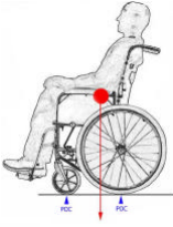
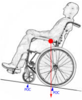
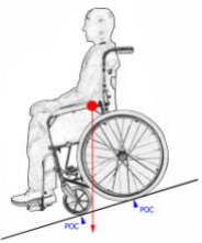
Sideways
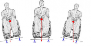
![]() The wheelchair setting, adjustable components, and the user’s weight distribution determine the wheelchair stability (Liu et al., 2010).
The wheelchair setting, adjustable components, and the user’s weight distribution determine the wheelchair stability (Liu et al., 2010).
Apparatus
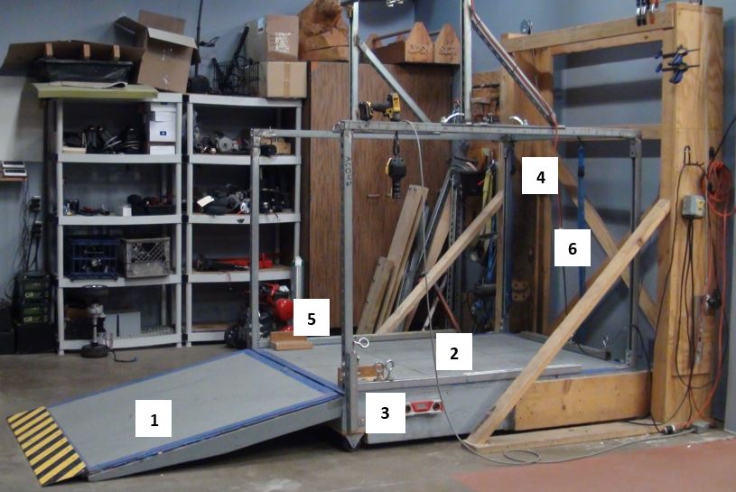
Figure 1. Static Stability machine. 1. Ramp, 2. Platform , 3. Digital protractor, 4. Hoist lift to adjust tilt angle, 5. Blocks, 6. Straps
The testing apparatus consists of:
- Ramp allows access to the wheelchair into the platform
- A flat platform plane that is wide, large and strong enough to position and support the wheelchair and the test dummy on it. The surface of the platform shown in the figure above has a layer of non-skid paint that prevents the wheelchair from rolling and sliding without affecting its tipping.
- Digital protractor to determine the tilt degree. It needs to be read at 0.10-degree increments. This tool can be replaced with a different angle measurement tool.
- The hoist lift raises and lowers the platform from the back end and increases/decreases the tilting angle of the platform where the wheelchair will be placed.
- Straps and blocks, as needed to prevent the wheelchair from rolling and sliding.
- Test dummy. Use a test dummy with the maximum weight capacity reported by the manufacturer for each testing wheelchair.
Test set up
- Set up the wheelchair following the manufacturer’s specifications. If not specified, set up the wheelchair including all the components for regular use.
- Inflate tires as recommended pressure, generally on the side of the tire, and inflate the tires to the pressure recommended by the manufacturer. If there is no pressure recommended, inflate it to the maximum pressure recommended by the manufacturer.
- Apply and adjust brakes.
- Remove any loose cushions.
- Set the adjustable components to the most and least stable configuration for the downhill/uphill or sideways stability test. See table 1.
- Adjust the wheelchair
Table 1. Component Configurations for Forward, Rearward and Lateral Stability
| Adjustable wheelchair component | Forward stability (downhill) | Rearward stability (uphill) | Lateral stability (sideways) | |||
| Least stable | Most stable | Least stable | Most stable | Least stable | Most stable | |
| Rear-wheel position, fore-aft | Forward | Back | Forward | Back | ||
| Rear-wheel position, camber | – | – | – | – | Narrowest track | Widest track |
| Caster attachment to frame, fore-aft | Back | Forward | Back | Forward | Back | Forward |
| Caster attachment to frame, inside-outside | – | – | – | – | Inside | Outside |
| Seat position, fore-aft | Forward | Back | Back | Forward | Forward | Back |
| Seat position, vertical | High | Low | High | Low | High | Low |
| Seat position, tilt | Upright | Back | Back | Upright | Upright | Back |
| Seat-back position, fore-aft | Forward | Back | Back | Forward | – | – |
| Seat-back position, recline | Upright | Back | Back | Upright | Upright | Back |
Table adapted from Rentschler, 2002.
Place the test dummy in the wheelchair
- Use a test dummy with a mass that matches the maximum mass capacity recommended by the wheelchair manufacturer.
- Secure the test dummy to the wheelchair in an upright position. Add straps as needed.
Tests to perform
Renstchler, 2002 mentioned steps for each test, so we recommend that before you proceed with testing, it is important to identify the tests to perform.
- Test 1.If the wheelchair has two front wheels, measure the forward tipping angles.
- Test 2.If the wheelchair has two rear wheels, measure the rearward tipping angles. Besides, if the wheelchair has rear antitip devices then perform the tests with the anti-tippers.
- Test 3.Test the wheelchair sideways with the wheelchair in the least and most stable configurations to measure sideways tipping angles.
For all cases:
- If the wheelchair has lockable wheels, then perform the tests with the wheels locked and unlocked in the least and most stable configurations.
- If the wheelchair has unlockable wheels, then perform the tests with the wheels unlocked in the least and most stable configurations.
Important: “The higher the tipping angle, the more stable is the wheelchair-user combination” (Kirby & Dupuis, 1999).
Test 1: Forward stability
a) With wheels locked
- Set wheelchair components in the least or most stable configuration for forward stability, see Table 1, and place the test dummy in the wheelchair.
- Place the wheelchair in the platform facing down the slope (when the platform increases its inclination).
- Lock the downhill wheels (the wheels at the lowest end of the platform).
- Use straps or wooden blocks to prevent the wheelchair from rolling or sliding, if needed, but leave them loose enough so that the wheelchair is free to tip. If the wheelchair is too big or too heavy, add a strap around the wheel to prevent it from sliding.
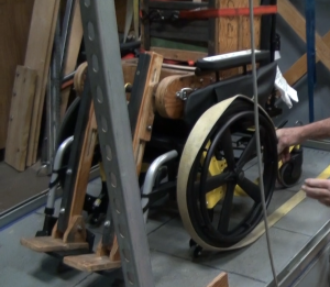
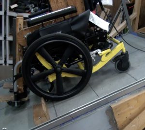
- Raise the platform until all the uphill wheels (at the highest point of the platform) are not in contact with the platform. The following video shows this step.
- Measure the angle between the horizontal and the test plane in degrees. This is the tipping angle or stability value. Record this value.
- Lower the test plane completely.
If you did the test with the wheelchair on the most stable configuration, repeat all the steps after having the wheelchair set up in the least stable configuration.
b) With wheels unlocked
- Set wheelchair components in the least or most stable configuration for forward stability, see Table 1, and place the test dummy in the wheelchair.
- Place the wheelchair in the platform facing down the slope (when the platform increases its inclination
- Repeat steps 4 to 7 on Test 1 a).
If you did the test with the wheelchair on the most stable configuration, repeat all the steps after having the wheelchair set up in the least stable configuration.
Test 2: Rearward stability
a) With wheels locked
- Set wheelchair components in the least or most stable configuration for rearward stability, see Table 1, and place the test dummy in the wheelchair.
- Place the wheelchair in the platform facing up the slope (when the platform increases its inclination).
- Lock the downhill wheels (the wheels at the lowest end of the platform).
- Use straps or wooden blocks to prevent the wheelchair from rolling or sliding, if needed, but leave them loose enough so that the wheelchair is free to tip. If the wheelchair is too big or too heavy, add a strap around the wheel to prevent it from sliding. See images on step 4 under Test 1 a).
- Raise the test plane until the uphill wheels (at the highest point of the platform) stop being in contact with the test plane. See the video on step 4 under Test 1 a).
- Measure the angle between the horizontal and the test plane in degrees. This is the tipping angle or stability value. Record this value.
- Lower the test plane completely.
If you did the test with the wheelchair on the most stable configuration, repeat all the steps after having the wheelchair set up in the least stable configuration.
b) With wheels unlocked
- Set wheelchair components in the least stable configuration for rearward stability, see Table 1, and place the wheelchair with the test plane in horizontal.
- Place the test dummy in the wheelchair
- Repeat steps 4 to 7 on Test 2 a).
If you did the test with the wheelchair on the most stable configuration, repeat all the steps after having the wheelchair set up in the least stable configuration.
c) With Antitip devices
For this test tip back the wheelchair so that the antitip devices are in contact with the test plane.
- Set the rear wheels as to the rearmost position possible according to the manufacturer.
- Set wheelchair components in the least or most stable configuration for rearward stability, see Table 1, and place the wheelchair with the platform.
- Set the antitip devices in the least or most stable configuration specified by the manufacturer. Do not adjust the antitip devices to a position in which they are ineffective.
- Place the test dummy in the wheelchair
- Repeat steps 4 to 7 on Test 2 a).
If you did the test with the wheelchair on the most stable configuration, repeat all the steps after having the wheelchair set up in the least stable configuration.
Test 3: Sideways stability
1.Set wheelchair components in the least or most stable configuration for sideways stability, see Table 1, and place the wheelchair with the test plane in horizontal.
2.Place the test dummy in the wheelchair
3.Place the wheelchair on the test place facing across the slope when the test plane increases its inclination.
4.Lock all lockable wheels
5.Use straps or wooden blocks to prevent the wheelchair from rolling or sliding.
6.Raise the test plane until the rear wheels stop being in contact with the test plane. If you used the piece of paper, it will slide under the rear wheel.
7.Measure the angle between the horizontal and the test plane in degrees. This is the tipping angle or stability value. Record this value.
8.Lower the test plane completely.
If you did the test with the wheelchair on the most stable configuration, repeat all the steps after having the wheelchair set up in the least stable configuration.
References
Kirby, R. L., Ackroyd-Stolarz, S. A., Brown, M. G., Kirkland, S. A., & MacLeod, D. A. (1994). Wheelchair-related accidents caused by tips and falls among noninstitutionalized users of manually propelled wheelchairs in Nova Scotia. American Journal of Physical Medicine & Rehabilitation, 73(5), 319–330. https://doi.org/10.1097/00002060-199409000-00004
Liu, H.-Y., Pearlman, J., Cooper, R., Hong, E.-K., Wang, H., Salatin, B., & Cooper, R. A. (2010). Evaluation of aluminum ultralight rigid wheelchairs versus other ultralight wheelchairs using ANSI/RESNA standards. Journal of Rehabilitation Research and Development, 47(5), 441–456. https://doi.org/10.1682/JRRD.2009.08.0137
Medicines and Healthcare Products Regulatory Agency. (2004). Guidance on the stability of wheelchairs. Department of Health. http://www.unece.org/fileadmin/DAM/trans/doc/2004/wp29grsg/GRSG-ig-access-03-10.pdf
Rentschler, A. J. (2002). Analysis of the ANSI/RESNA Wheelchair Standards: A Comparison Study of Five Different Types of Electric Powered Wheelchairs. http://pitt.summon.serialssolutions.com/2.0.0/link/0/eLvHCXMwdV1NawIxEB1aeintoaKl1irzB6zpJnGT3hZ1qRcR7H3J5oMKxUK1h9I_bxJXWcVeAzMkDzKTmczMA6DJM-mf2ARHqfbOTFDjRcSLlVpyraQWJSPMRNKIepHlgfnrZAjSz_8_M14Pp6GX-pIyuusYP5pXGv1Ffgc349o_dwMu7KoJf_sBIPjl0L-7MJstpgOPwCxDbxPtp_5Qy29cVMH9-hUzHB1oAjFU_P0G0dwbKBxXxCYbDJFkVDmJjDZLjfPAfGZNTem6BZ188j5664etFlXOpqhOk9zDrQqV7qtN7IgzD4DCak5l6TjnKXO8VEaVPqpynAzlUFrShuY5VW3oHi3vISxYkvKUiMfzYh24jvwnMenwBFfOXwrb3QHbiyhvASOGkvk
Thomas, L., Borisoff, J., & Sparrey, C. J. (2018). Manual wheelchair downhill stability: An analysis of factors affecting tip probability. Journal of NeuroEngineering and Rehabilitation, 15(1), 95–12. https://doi.org/10.1186/s12984-018-0450-3
Acknowledgments
Bill Ammer from Ammer Consulting for the support and contribution to this article.

